Does the arm's reach cover your pick and place poses?
Check tool orientation, TCP offset, approach paths and assembly clearance before choosing a robot arm for loading or tray handling.
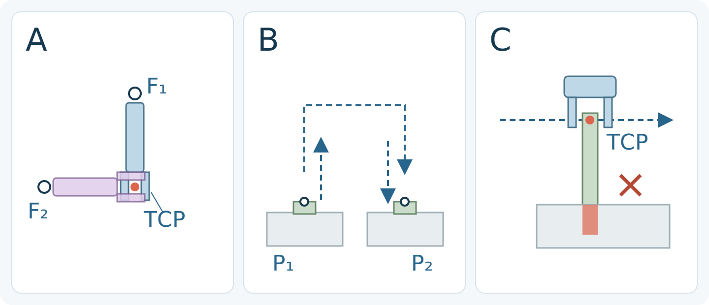
Treat reach as a screening number
No. A target inside the advertised reach does not establish that the arm can hold the gripper at the required angle. In its g-Series Operating Space chapter, Universal Robots distinguishes recommended reach from a larger maximum working area with restrictions on tool orientation.
For loading or tray handling, define each target as a position plus the required gripper orientation. Check the selected arm's own working-area drawing, joint limits and mounting arrangement. The UR description is not a working envelope for CBOXTEC arms.
- Universal Robots — Operating Space, g-Series User Manual (SW10_15) · Accessed 2026-10-13
Locate the TCP on the assembled tool
Universal Robots' PolyScope SW5_22 manual defines the tool center point (TCP) with a position offset and rotation relative to the tool-flange center. A waypoint stores both the TCP position and its orientation.
Draw the adapter, gripper and fingers, then locate the intended tool point relative to the flange. Rotating the tool while keeping that point fixed can require a different flange position. Tool length therefore cannot simply be added to the arm's advertised reach.
- Universal Robots — TCP Configuration, PolyScope (SW5_22) · Accessed 2026-10-13
Check approach and withdrawal, not just endpoints
In the UR5e SW5_19 manual, MoveJ is calculated in joint space and can produce a curved tool path; MoveL moves the TCP on a straight line between waypoints. The same pick and place endpoints do not specify the same path.
Include the approach, grasp, lift, transfer, placement and retreat poses. Check joint limits, required orientation and obstacle clearance along each proposed segment. Two reachable endpoints do not prove that the intervening motion is feasible.
- Universal Robots — Basic Program Nodes: Move, UR5e manual (SW5_19) · Accessed 2026-10-13
Check space around the whole moving assembly
Compare the gripper body, open fingers, held part and cable or hose routing with tray rims and surrounding equipment. A clear TCP line can still leave another part of the assembly in collision. Include positioning variation and part tolerances; there is no clearance value that fits every application.
The UR g-Series chapter also identifies singularities associated with outer and inner workspace limits and wrist alignment. Review such restrictions in the selected arm's documentation. A simulation using accurate geometry can help assess a layout, but does not establish installation safety or actual cycle time.
- Universal Robots — Operating Space, g-Series User Manual (SW10_15) · Accessed 2026-10-13
Ask for a pose review before choosing the arm
Send a dimensioned layout showing the base location, mounting height, pick and place heights, approach directions and required tool orientations. Include the assembled adapter and gripper geometry, TCP offset, part shape and cable routing. State which tool rotations are required and which may change.
Ask the supplier to identify reachable poses, feasible paths and any joint-limit or clearance concerns for the specific model. CBOXTEC Robotics supplies robot arms and grippers; model selection needs these details as well as a reach figure. A reachability review does not certify the installation or guarantee a cycle time.
Manufacturer references
- Universal Robots — Operating Space, g-Series User Manual (SW10_15) · Accessed 2026-10-13
- Universal Robots — TCP Configuration, PolyScope (SW5_22) · Accessed 2026-10-13
- Universal Robots — Basic Program Nodes: Move, UR5e manual (SW5_19) · Accessed 2026-10-13